
It does however require more complicated software to interpret the input e.g., hysteresis and debounce could be implemented with thresholds such as:įigure 2 – Connecting SPDT switch to MCU.

Here is an alternative way to connect the SPDT to the MCU which is useful when running out of pins because it only requires one input pin. You need to connect the center pin to either ground +5V, as discussed above. It would make sense to use it as a digital input, since you need it to give you 2 states, open and closed.
ON OFF ON SWITCH WIRING HOW TO
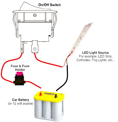
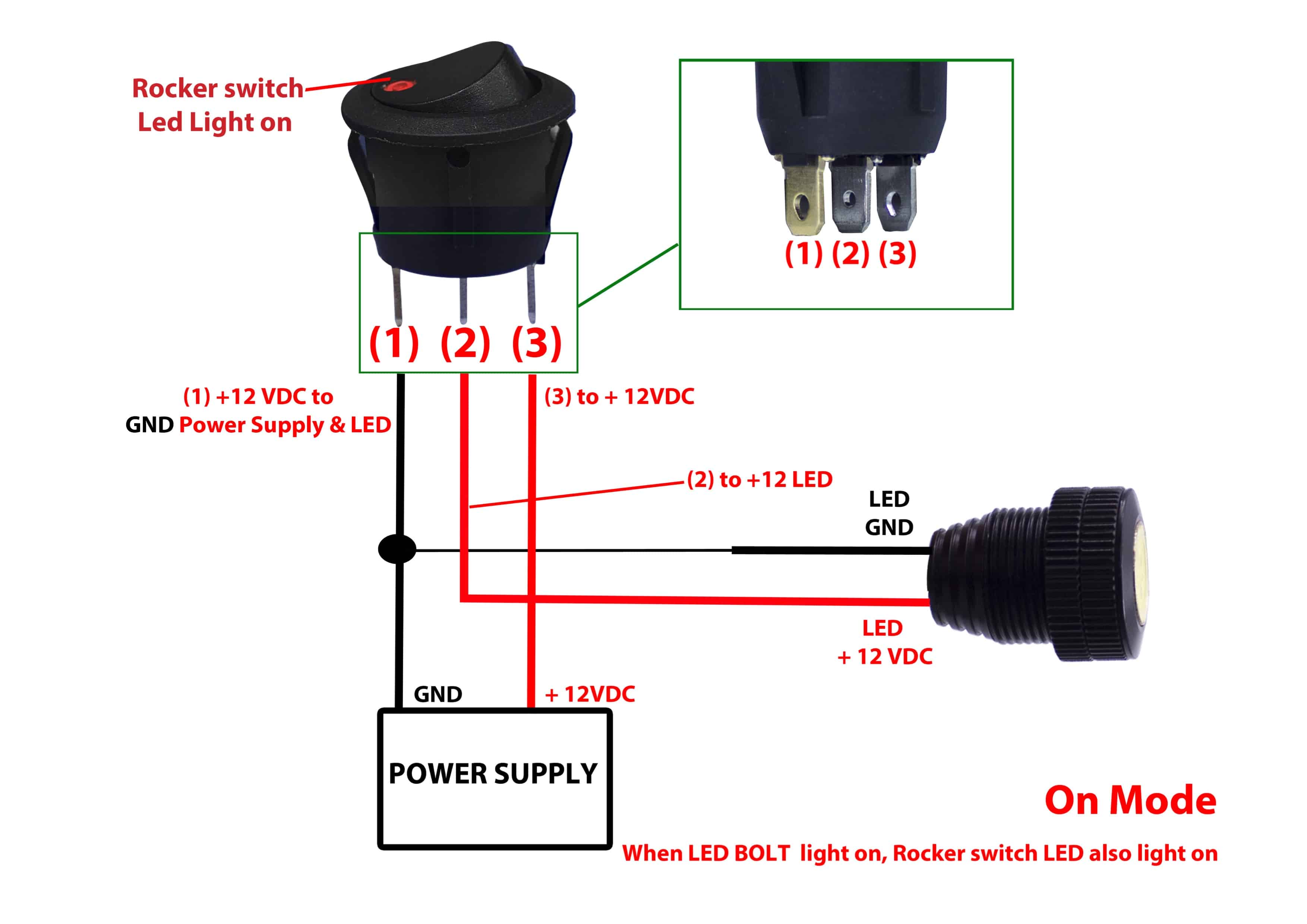
You talk about how to wire a switch to switch power to a pair of lights directly, without using a microcontroller.
ON OFF ON SWITCH WIRING PC
(And wiring it will be a little painful without a breadboard or PC board.) It is also possible to wire your switches using INPUT mode, not INPUT_PULLUP, and have them read LOW when the switch is open, and HIGH when closed, but to do that you'll need external pull-down resistors. Flip the switch the other way and it would connect the other pin to ground, at that other pin would drop from HIGH to LOW. That would connect that Arduino pin to ground, and the reading on the pin would drop from HIGH to LOW. If you flip the switch one way, it would connect one outer pin to the center pin. You'd then attach those to pins to the two outer pins of your switch, and attach the center pin to ground (GND). That might seem a little confusing, but it means you don't need external resistors. When the button is pressed/switch is closed, it reads LOW. If you don't connect anything to the pin, it reads as HIGH. That connects the inputs internally through a resistor to +5V. I suggest setting the Arduino input pins to INPUT_PULLUP mode. You need to force each input to either ground or +5V when it's not connected to anything, or it will "float" and you'll get semi-random high and low readings.

If you want the Leonardo to read the state of the switch as 2 separate switches/button presses, wire the 2 outer pins of the switch to 2 separate digital inputs on the Arduino. When flipped one way, it connects the center pin to one of the outside pins, and when flipped the other way, it connects the center pin to the other outside pin. You link to an SPDT (single pole, double throw) switch.

Instead, you want to use your switch to send information to your Arduino. You talk about wiring a switch to control lights directly. One final note - I'm not using a breadboard, but connecting the wires directly from the switch to the board. Is a wire from the switch to GND not required?.Is the output of the switch considered digital or analog?.Is the above wiring example correct for my use case?.The end goal is to have the two ON positions read as separate button presses (eventually using a joystick library, in case that changes how the switch needs to be wired). I don't want to power anything in a literal sense, I only want to have the Leonardo read the output of the switch. Those lights also have a ground connection. Generic three-pin SPDT wiring diagrams I've found suggest that the two outer pins should be connected to separate lights and the middle pin should be connected to the power source. This is the switch in question: E-Switch 200MSP4T1B1M1QE I would like to read the output of an on-off-on switch with my Leonardo board, but I have very little knowledge of electronics and don't know how to wire it up.


 0 kommentar(er)
